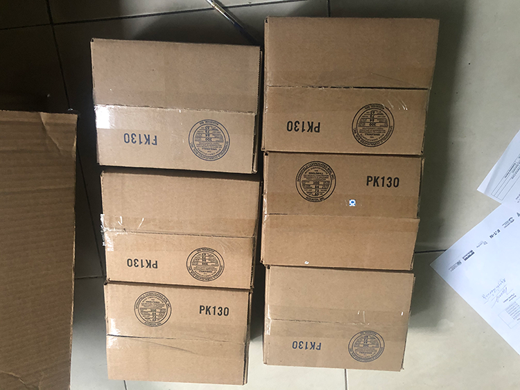
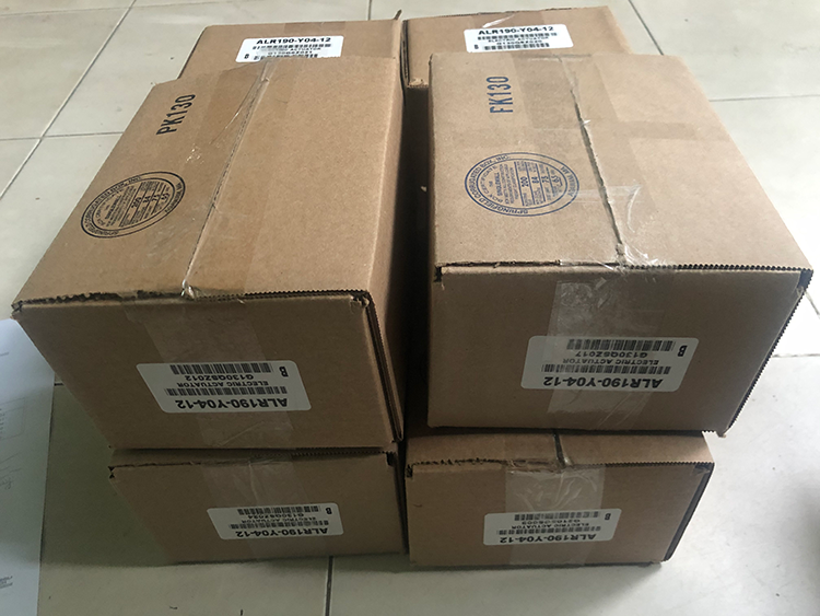
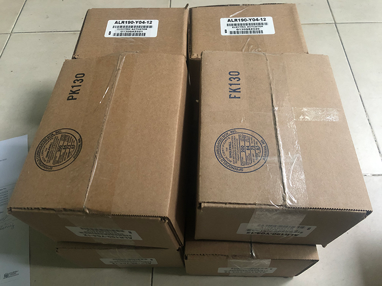
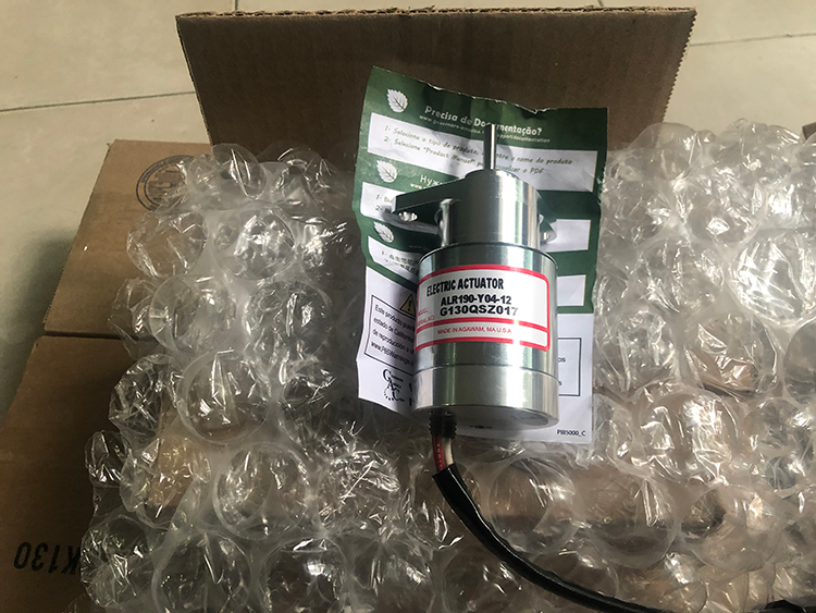
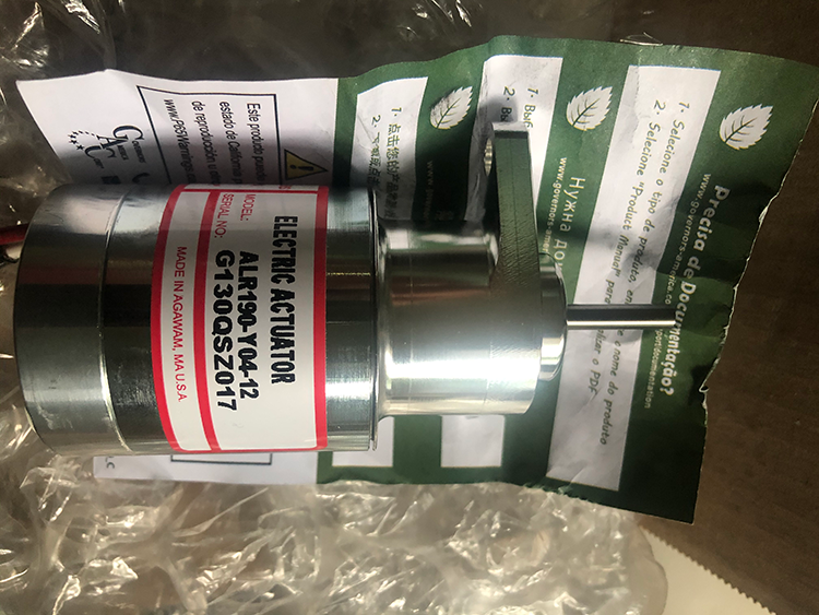
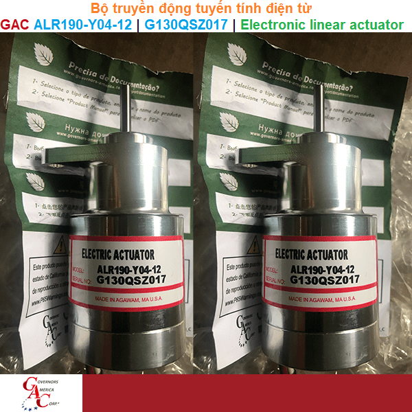
Bộ truyền động tuyến tính điện từ GAC ALR190-Y04-12 | G130QSZ017 | Electronic linear actuator
Specifications
Electrical
Operating voltage: 12V DC
Nomal operating current: 3.2A 12VDC
Maximum current: 5.0A 12VDC
Continuously rated: 2.5A 24VDC
Coil resistance: 1.8 +/- 0.2 ohms
Connection 16 AWG: (0.8 mm2) leads
 Environmental
Operating temperature range: -40oF to 200oF (-40oC to 95oC)
Relative humidity: up to 100%
Vibration: +/- 4 G, 25 to 100Hz
Shock: 20 G Peak, 11msec
Alsurface finishes: Fungus proof and corrosion resistant
Sealing: Oil, Water, and Dust resistant
 Physical
Weight: 1.3 lb (0.59 kg)
Diagrams
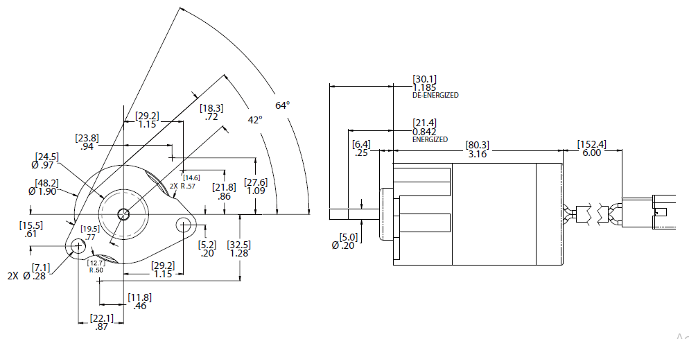
ALR Installation instructions
WARNINGS
Engine should be equipped with an independent shut down device to prevent overspeed, which can cause equipment damage or personal injury.
Do not attempt this installation with the engine running or serious damage may occur to the equipment or personnel.
NOTE
The ALR190-M04 is the only Actuator that has shims included with product.
INSTALLATION PROCEDURE FOR ALR190-M04
WARNING
The ALR190-M unit must be adjusted for proper operation. If the installation procedure is not followed, damage to the actuator and or injection pump is possible.
1. Index mark the OEM shutdown solenoid directly behind the locknut with a marker or scribe before loosening the locknut. This mark is important. A precise measurement (depth micrometer) will be taken after shutdown solenoid is removed from the injection pump housing.
2. Remove the wiring harness and loosen the solenoid locknut. Clean the area from dirt or grease. Loosen and remove solenoid from the injection pump housing using standard service cautions.
3. Move locknut on shutdown solenoid back to previously indexed mark (Step 1) and measure distance from the front side of locknut (side that was previously against injection pump housing) to the end of shutdown solenoid shaft. Record this measurement. The more precise this measurement (depth micrometer) the more precise the ALR actuator will perform.
4. Use the locknut from the old shut off solenoid and position it on the new ALR actuator the same distance as the old solenoid (Step 2).
*Shims are included with this actuator if needed to set position.
5. Clean threads and mounting surface of the ALR actuator. Install ALR into injection pump housing (no sealant required) until locknut
is flush with injection pump housing. If resistance is felt, remove ALR and inspect threads for dirt or burrs. Also use a clean lint free
rag to clean injection pump internal threads. A small amount of clean engine oil can be applied if desired. When locknut is flush with
injection pump housing tighten nut down.
6. Install wiring harness, start engine, adjust governor speed controller per PIB document.

INSTALLATION PROCEDURE FOR 190-F, 190-K, 190-Y
1. The actuator is installed in place of the engine’s stop solenoid. Remove the solenoid by first disconnecting the electrical leads at the
connector.
2. Cover and secure the engine harness leads as they are no longer needed.
3. Remove the two screws that attach the solenoid to the pump face. Save the screws and o-ring. They will be reused when attaching the actuator.
4. Install the o-ring into the counter bore on the pump face.
5. Install the actuator using the solenoid screws.
6. Attach the actuator leads from the speed control unit.
ALR TROUBESHOOTING
If the actuator fails to move to full fuel, make the following tests:
1. Measure battery voltage at the controller (see specification for the operating voltage).
2. Check linkage. Manually operate linkage to see that it is not sticking or binding.
If the actuator fails to move, make the following tests:
1. Measure the coil resistance between the actuator leads (see specification for resistance).
2. Measure the resistance between one lead of the actuator and the housing of the actuator. It should be infinity.
3. Energize the actuator to full fuel by following the procedure in the control unit publication. If the actuator does not move, it is defective.


 GAC ALR190-Y04-12 | G130QSZ017 | Electronic linear actuator -Bộ truyền động tuyến tính điện từGiá tốt nhất Xem...0909186879 Email